
This smart particulate matter sensor project by luftdaten.info could change the world. The project itself is open source and all the collected data is available for the public. The project only collects the particulate matter data. The idea is to involve as many people as possible to build up a crowd to collect as much data as possible from around the world.
This is the reason why I build my own particulate matter sensor and why I want to be a part of this project. I support the project with the data my sensor collects and hopefully with this how to guide. I started to translate the official assembly instruction published on the official project homepage (http://luftdaten.info/feinstaubsensor-bauen). I added some new and different parts with my own experiences I had.
The construction manual will guide you step by step through the whole project in less than one hour.
Now let’s start to build your own sensor and to contribute the data you collected to the project.
Shopping list
This are the parts you need to build your own particulate matter station. The sensor station costs round about 36 USD if you order all the parts in China. My experiences are very good with the shipping and quality of the goods shipped from China to Germany.
– NodeMCU ESP8266, CPU/WLAN
– SDS011 particulate matter (old model PPD42NS)
– DHT22, Digital Temperature And Humidity Sensor (optional)
– Jumper wires
– USB cable: 2m Micro-USB
– Switching Power Supply USB
– Cable ties
– Flexible transparent PVC tube with a diameter of 6mm
– Weather protection, Marley Silent HT arc (DN 75 87°) (Sorry this is a German link)
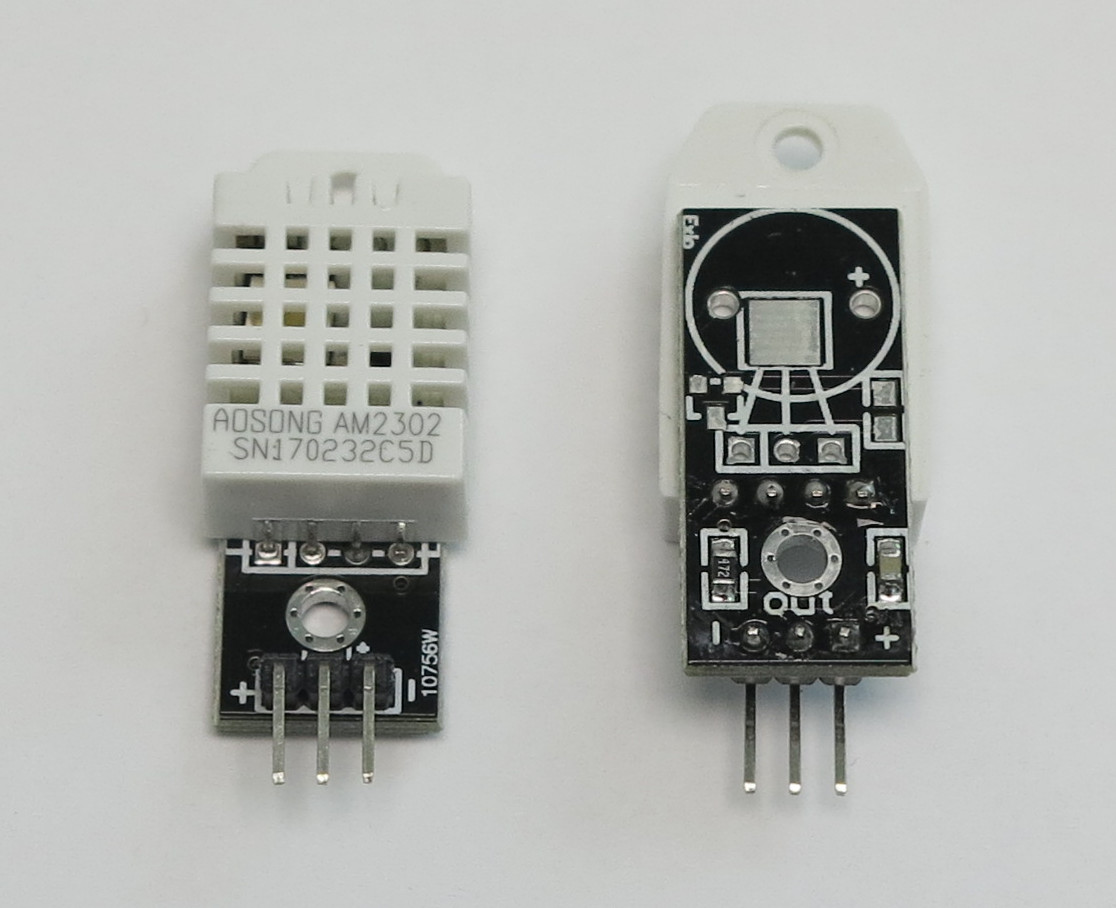
DHT22 sensor
Please buy the DHT22 sensor as shown in the picture below with the circuit board at the back. This sensor is easy to connect with the three pins and no need for an additional resistor.
DHT22 sensor
Assemble time and overview
To assemble the particulate matter sensor is very easy. The first step is to flash the latest firmware version on your NodeMCU board. Then in a second step you only need to plug seven wires between the NodeMCU board, the particulate matter sensor and the DHT22 sensor. Then you put all together into a case to protect the electronics from the weather. From my experience you only need round about 60 minutes to put flash the board, to put everything together and to check the wires two times.
There is no need to program or calibrate the sensor. The programs for the station is ready to run. The software is available as a single file you have to flash on the NodeMCU board. To flash the NodeMCU board is very easy and explained in detail below.
Connect the NodeMCU board with a Windows PC
Windows: I will explain in detail how you connect the NodeMCU board with a Windows 10 PC. You neet a microUSB calbe to communicate with the NodeMCU board. Windows will install a USB2serial driver itself after connecting the board. The NodeMCU board uses an ESP8266 with a CH341 chip. Windows 10 installs the right driver automatically. This was done in a few seconds on my PC.

CH340 device manager
Linux: Linux needs no special drivers. Linux normally supports the CH341 chip.
MacOS: For Sierra you could follow the following GitHub instruction: https://github.com/adrianmihalko/ch340g-ch34g-ch34x-mac-os-x-driver
Raspberry Pi: To communicate with the CH341 chip with a Raspberry Pi please follow this instruction: https://github.com/aperepel/raspberrypi-ch340-driver
Flash the ESP8266 firmware
Now you have to flash the firmware on your NodeMCU boad. Otherwise the board is not working together with the two sensors and the luftdaten.info project.
1. Download the “NodeMCU Flasher” firmware programmer EXE for windows (Win32/Win64) to flash the firmware file on your NodeMCU board: https://github.com/nodemcu/nodemcu-flasher
2. Download the lates version of the firmware which is published here: https://www.madavi.de/sensor/update/data/latest.bin
3. Now start the NodeMCU Flasher program and select the COM-Port on which Windows has detected your NodeMCU board.
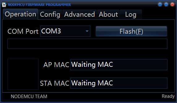
NodeMCU Firmeware Programmer waiting
4. Switch to the Config tab and select the firmware file “latest.bin” which you downloaded in step 2.
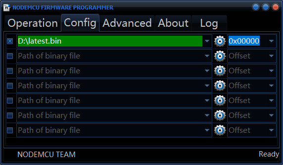
NodeMCU Firmeware Programmer latest bin
5. Select the right baudrate for the com port. It shoud be 115200 as shwon in the picture below.
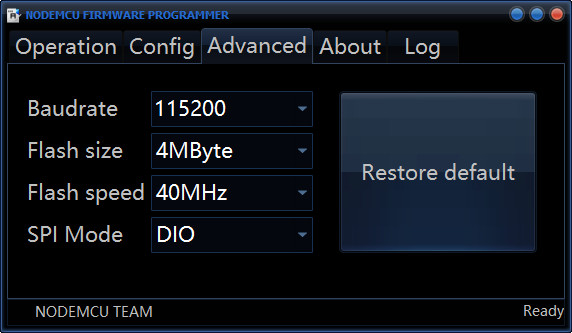
NodeMCU Firmeware Programmer baudrate
6. Now press the Flash (F) Button and the firmware will be flashed on your NodeMCU board. You will see a progress bar as you see it in the picture below.
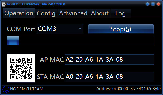
NodeMCU Firmeware Programmer flashing
The flash process will take less than a minute. After flashing your NodeMCU module the board is ready for the next step. The next step is to connect everything together with the jumper wires.
Attach the SDS011 sensor to the NodeMCU board
Now you need four female-to-female jumper wires to connect the NodeMCU board to the SDS011 particular matter sensor. The next pictures shows the NodeMCU board with the pins.
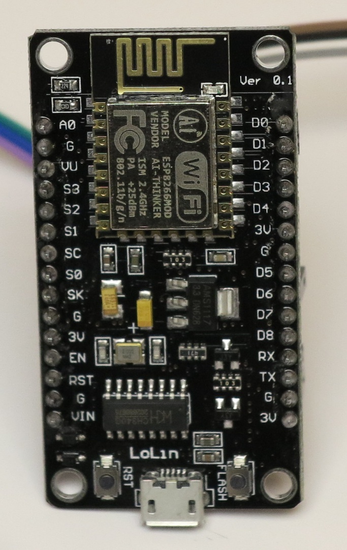
nodemcu v3 esp8266
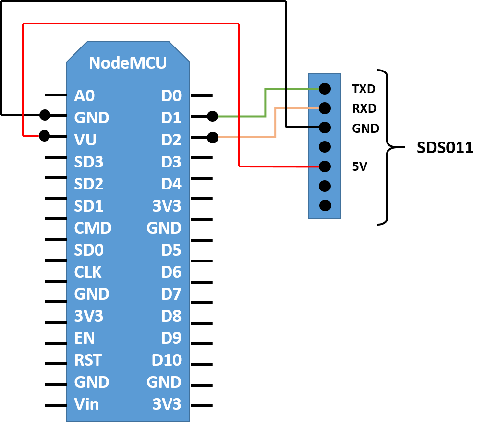
The list just explains which pin of the SDS011 is connected to which pin of the NodeMCU board
| SDS011 sensor | NodeMCU board | |
| SDS011 Pin 1 | -> | Pin D1 / GPIO5 |
| SDS011 Pin 2 | -> | Pin D2 / GPIO4 |
| SDS011 Pin 3 | -> | GND |
| SDS011 Pin 4 | -> | unused |
| SDS011 Pin 5 | -> | VU (NodeMCU v3) / VIN (NodeMCU v1,v2) |
| SDS011 Pin 6 | -> | unused |
| SDS011 Pin 7 | -> | unused |
The schematic drawing helps you to attach the SDS011 sensor to the NodeMCU board in a correct way.
drawing NodeMCU and SDS011
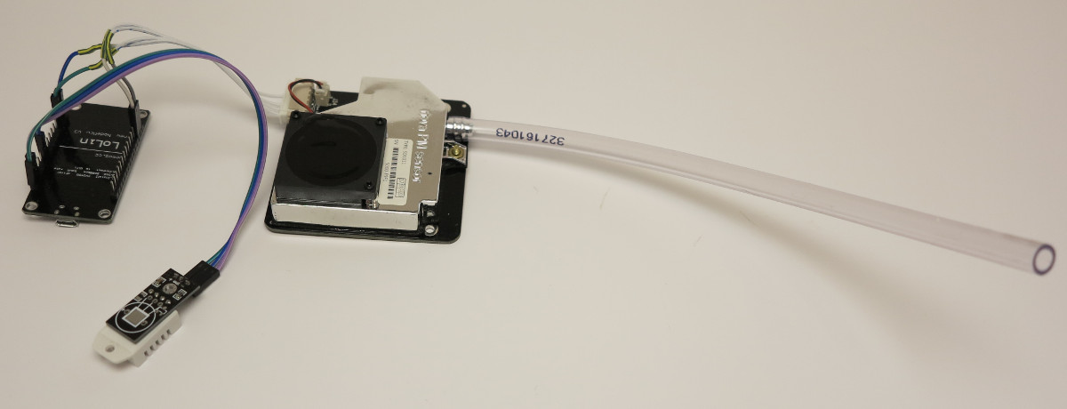
Now your NodeMCU and the SDS011 should look like mine with the four jumper wires.
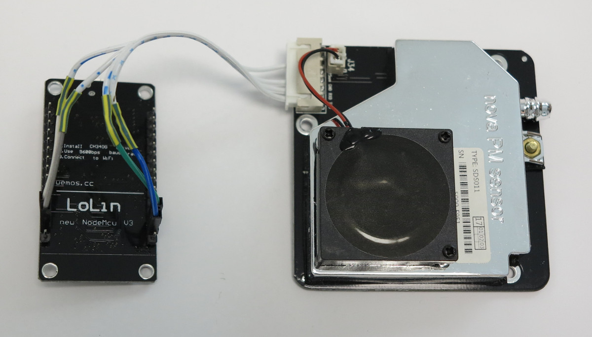
NodeMCU with the connected SDS011 sensor
Attach the DHT22 sensor with the NodeMCU board (optional)
To attach the DHT22 digital sensor you need three female-to-female jumper wires. I liked the idea to know the temperature outside and to add this information to the data stream which is send to the project. As I understood it is important to know the temperature and humidity to understand the particular matter behavior.
The list just explains which pin of the DHT22 is connected to which pin of the NodeMCU board
| DHT22 sensor | NodeMCU board | |
| DHT22 Pin 1 | -> | Pin 3V3 (3.3V) |
| DHT22 Pin 2 | -> | Pin D7 (GPIO13) |
| DHT22 Pin 3 | -> | unused |
| DHT22 Pin 4 | -> | Pin GND |
The shematic drawing shows how you have to set the three pins.
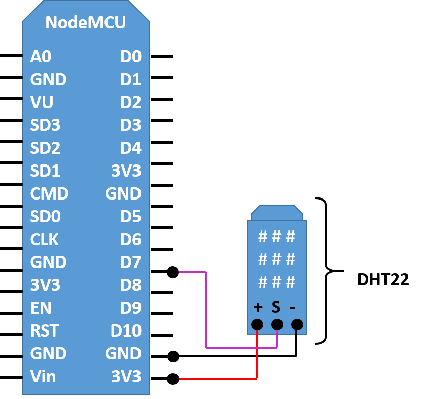
drawing NodeMCU and DHT22
Now your setup with the NodeMCU, SDS011 and DHT22 sensor should look like shown on the next picture.

NodeMCU with the connected DHT22 sensor
Flexible PVC tube
Cut a piece with a length of 30 cm of the flexible PVC tube with the 6mm diameter and connect it to the nozzle of the SDS011 sensor. This should now look like shown in the next picture.
ready assembled sensor
Your sensors are all connected to the NodeMCU board and it is time to put everything into an enclosure to protect the electronics from the weather.
Weather protection
To protect the two sensors and the NodeMCU board from the weather you slide the modules in a PVC pipe. This is the way which the project luftdaten.info has explained to work best. The picture below shows the installation with these two tubes. You typically get these kind of tubes in a construction market.
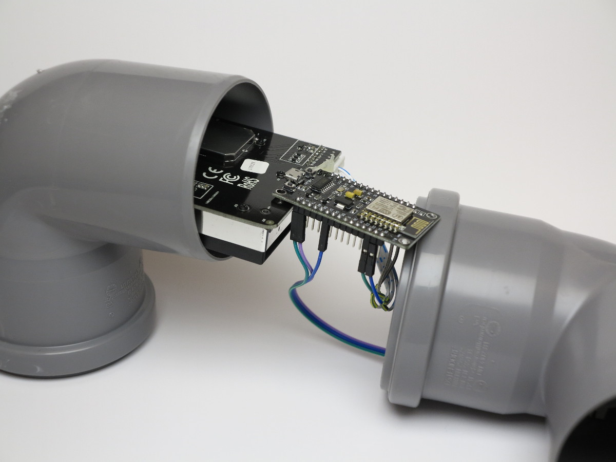
particulate matter sensor station
Important for the SDS011 particulate matter sensor is, that the fan is on the bottom of the board. The Node MCU board could be tightened with a cable tie on the SDS011 sensor. The DHT22 sensor is inside the tube to measures the temperature and humidity.
Ready assembled the particulate matter sensor needs to be connected via microUSB cable with a 5V supply. It is important for the project that the sensor runs 24 houers 7 days a week.
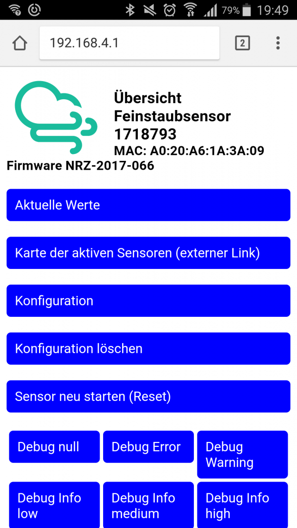
WIFI configuration
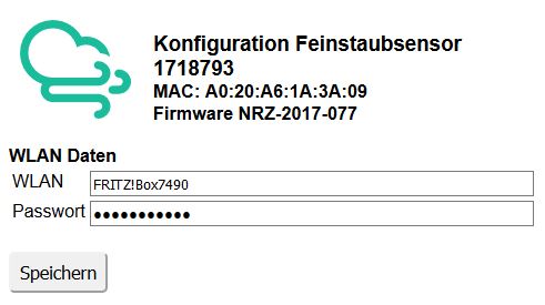
After powering up the sensor station with the microUSB cable the station will open an access point. This may take a few minutes. You should see an open access point in your list of available WIFI networks. It should be named something like “Feinstaubsensor-1234567”. The number at the end is the ID of your sensor. Please write down these number / ID. You will need the ID to for the luftdaten.info project to identify your sensor station. Only with the ID you could add your sensor to the map and contribute the collected data.
Connect for example your smartphone with the sensor station WIFI and open the following URL to load the configuration menu of your sensor.
URL: http://192.168.4.1
Please click on the button “Konfiguration” which means configuration and add your local WIFI.
HotSpot – configure the WIFI
Please select your local WLAN (WIFI) via the SSID / name of you network. Then type the password into the field called “Passwort”. Then type “Speichern” to save the login information and “Sensorneustarten” (restart) the NodeMCU. Now your sensor is online.
setup the wifi connection
After the sensor is connect with your local WIFI you should find the local IP address of the sensor station for example in the menu of your router. By opening the sensors IP address you could connect to your sensor.
The access point will only be available one again if the connection to your configured WIFI gets lost.
Add your sensor to the map
To add your sensor to the luftdaten.info sensor map you have to write a short e-mail to the following address with some information’s about your sensor:
Email to rajko@codefor.de with the following informations:
- Your ID of the ESP8266 (NodeMCU) –> The ID was shown in the WIFI Accesspoint and you wrote it down.
- Your address: Street, number, zip-code and town. –> They will create the coordinates of your sensor to add the sensor to the map. Your data will not be published and the coordinates are rounded.
- The environment of your station – street side, view like a field or your yard, the traffic intensity, meters above ground.
- Your e-mail address. The e-mail address will not be published for the public. But they need the e-mail address for configuration and as your login for the project homepage.
- If possible a picture of your sensor installation. The picture will not be published.
After sending the e-mail your will get a confirmation e-mail and your sensor will be added to the map.
To open the map just follow the link: http://deutschland.maps.luftdaten.info/
Update June 2017
I build with a friend three additional sensors for other friends and collegues. The picture shows our electronic components we bought for the three sensor stations.
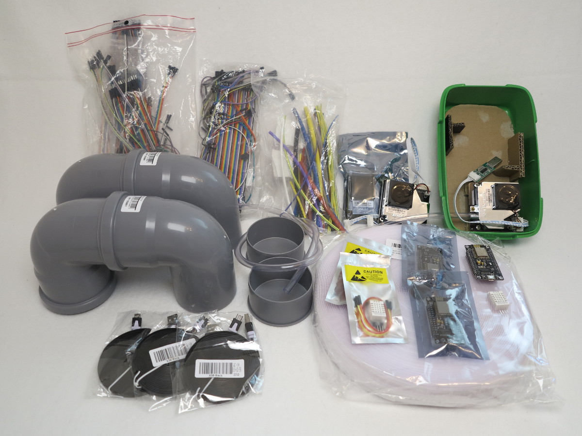
Particulate Matter Sensor – components
The next picture shows the soldering station with the ready assembled sensors.
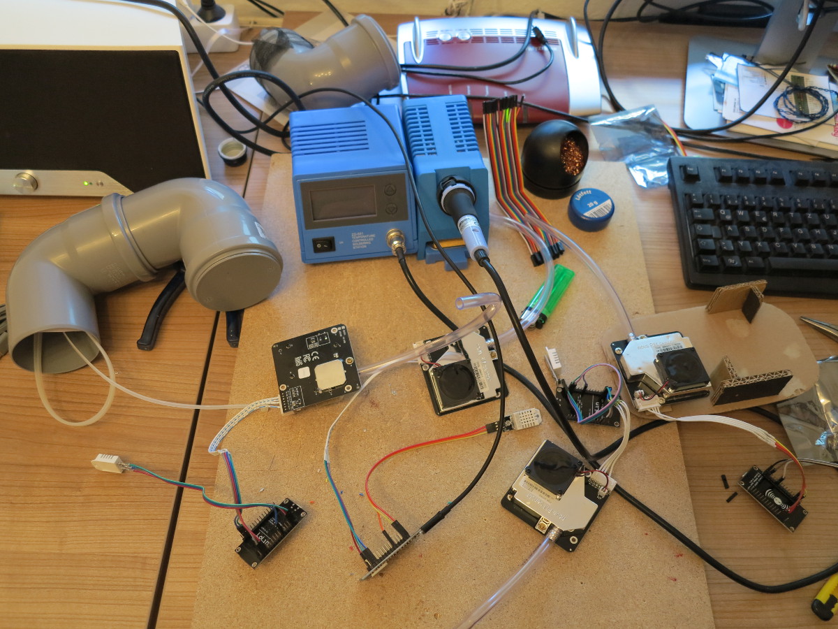
Particulate Matter Sensor – ready
Summary
At the beginning of this project I had some problems to flash the firmware on the NodeMCU. But with the “NodeMCU Flasher” firmware programmer it was very easy. Then the assembly of the sensor station was done in less than an hour. Now I am able to check the air quality around my flat and to check the temperature. I like the idea of the project and to collect data for hopefully many very interesting projects.


Hello I’m building these to measure levels in our town. I’m having trouble finding the 2 x big grey bend pipes that everything is stored in. Can u suggest where to get them? Thanks
Are these instructions still applicable? I cannot flash the firmware on Windows 10.
Can you please be more specific on the model and type of the NodeMCU ESP8266, CPU/WLAN? The link you provide shows many, many different versions of this piece of hardware. I ordered one that is labelled nodemcu Amica cp2102 and it fails to load any drivers in windows 10.
You need to install theCP2102 driver:
https://lastminuteengineers.com/esp8266-nodemcu-arduino-tutorial/.
I flashed it on Windows 10.
Also, the interface can be switched to English.
I use a NodeMCU ESP8266 from AliExpress. It should work on any model I guess.
Unfortunately the web interface is only in German despite it appearing to have a link to use English, which doesn’t work. So sorry, a nice tutorial but in the end you must understand German to use it.